The POG2 is a superb piece of kit, however I have always fancied being able to control it with an expression pedal. I saw Skjarpe's mod so started there. Its a fairly basic modification but I took it a bit further. Luckily I didn't see £200 go up in smoke, the thing actually worked so I thought I'd put a little what I did guide together.
I'm not an electronics expert so I'm sure this circuit is not the simplest most elegant solution, however it works for me! If anyone else is thinking of doing it just make sure you prototype it up first and check and measure everything before you attach it to the POG board, make sure you are getting the voltages you expect where you expect them before you even open the POG up!
The mod involves adding an expression pedal and 4 switches. The switches allow me to select which parameters the mod pedal will alter. I can select a combination of the following ; Low octaves(-1&-2 sliders), High octaves(+1&+2 sliders), LPF and detune. The maximum level (i.e. toe down on exp pedal) is set by the slider and the exp pedal allows control over this range.
I copied the basic idea from Skjarpe's circuit. I needed to use an op amp which worked from a single supply and allowed its output to go down to the 0v rail. I had some LM324's which are quad op amps. This gave me the idea to control 4 parameters.
Each fader on the POG varies a control voltage between 0v-5v. The exp pedal varies the op amp output between ~0v and 5V, so by using the output of the op amp as the 100% level of the pog faders, the fader can set the max level and the exp pedal will control the overall level up to this point.
I used an M-Audio expression pedal, a standard stereo jack socket and SPDT switches.
The power supply to the op amp chip is set to ~6.5V by the potential divider, this is so the maximum the op amp will ever output is ~5V. If for some reason one of the op amp inputs goes open circuit the op amp will go as close to the +ve rail as it can, the LM324 can only get about 1.5v below the positive rail, hence a 6.5v + rail.
I wanted to use switches to assign faders to the mod pedal. Part of the circuit outputs the same signal as would be seen by the exp pedal at 100%, this way I could switch the op amp inputs between this 100% circuit and the mod pedal signal circuit . This could have also been done by switching the signal to the fader between op amp output and 5v, I'm not quite sure why I did it the way I did!
The circuit is shown below, the 5Spice program wouldn't do switches so I've had to kind of draw them on, you get the idea tho. The "EXP_v" tag is the signal from the expression pedal, the "5V Value" tag is the 100% value.

I built up the circuit on veroboard and used solid core cable for the flying leads.

Check the outputs are giving you the voltages you expect (0-5v).
Now take the board out of the pog unit. You will need to remove all the white knobs then unscrew the bolts on the jack sockets, the buttons and the preset knob. Unscrew the 3 screws holding the board in, and the board should then slide out with some gentle persuasion.
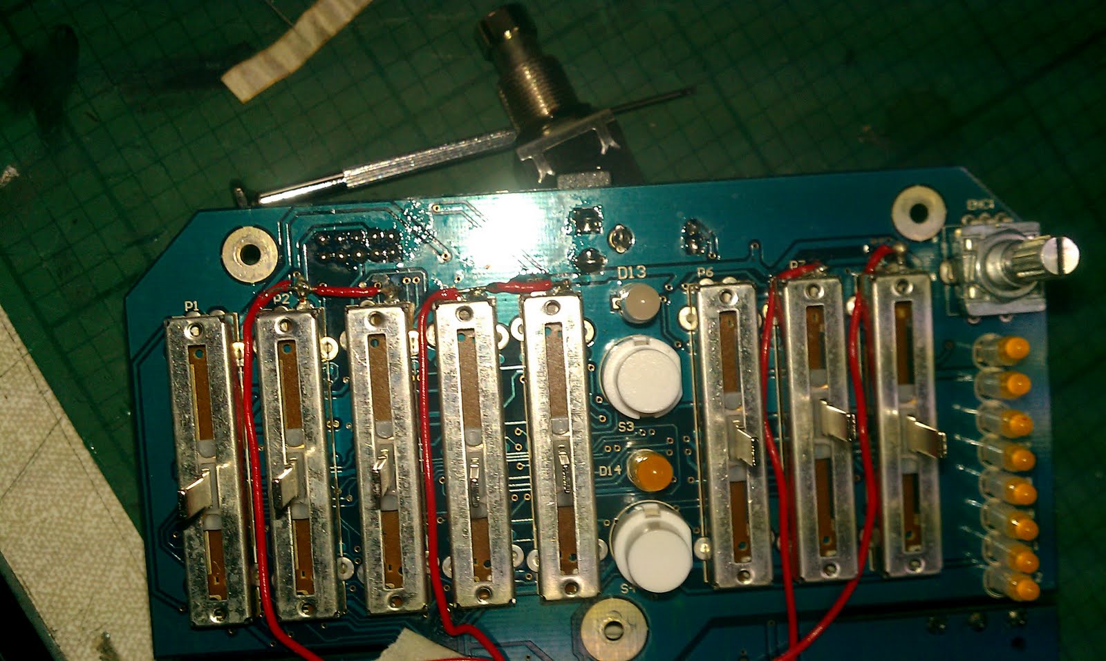
Locate the “5v” terminals on the faders as shown in the pic below. As you look at the board there will be the top right terminals. You can check they are the right ones with a continuity meter. The 5v terminals on all the faders will show continuity.
Locate the faders you want to add the mod to. You’ve now got to carefully remove these terminals from the board without heating the board up too much or damaging anything. You can probably see I didn’t manage the neatest job in the world. I managed to pull the fader up by about a mill by heating up the solder points one at a time. I then snipped the terminal at the board and bent it horizontal. You won’t have to use the connection on the board anymore so don’t worry too much about that.

The op amp flying leads can then be connected to the raised terminals. I used op amp 1 to control the 2 low octave faders, 2 to control the upper octaves, 3 on the LPF and 4 on the detune. I used strips of masking tape then superglue to hold the wires in place and secure the connections. Make sure that the terminal or connection does not touch the metal cover of the fader. Again I used a bad of superglue to keep the terminal away from the fader case. Make sure you have labelled the op amp output leads with the switch wires so you know what is controlling what.

Now do another check, with the POG off power up the op amp circuit and make sure that the output leads are all giving voltages from 0-5v as you would expect depending on the op amp inputs.
Now drill the holes in the box for the switches and exp jack socket. Unfortunately I couldn’t mount the exp jack in line with the input socket as there wasn’t enough room, it sits slightly above. Space is tight so measure twice etc. Solder up the switches so the middle terminal goes to the op amp input and the sides go to either the 100% signal or the EXP signal. In the picture below I've put the switches in the box from the outside to make access easier, these could then be removed in 1 "switch strip".

The 9V and 0V supplies can be taken from the 9V jack on the board. The 9V pad is found on the same side of the boards as the faders(see pic), the 0v is next to the power socket on the reverse of the board. The 5v power can be taken from the 5v pads for any of the faders, its easier if you use the connections on the rear of the board. I took mine off the 1st fader.

Now reassemble everything and mount your new board. I used some gasket material which wrapped round the board and held tight once the base was back on.


Put your knobs back on and enjoy!
